Friday, April 19, 2013

Optical Bar Cameras

[Update: I'd like to thank Phil Pressel, John Gregor, and Gordon Petrie for their corrections to this post.  The changes required have been so extensive I have not marked them.]

[Update 2: Phil Pressel just released his book Meeting the Challenge: The Hexagon KH-9 Reconnaissance Satellite (get it at AIAA or Amazon).  I've ordered it and will post a review after I get it.]

From 1957 to 1965, a high tech startup called Itek made the world's most sophisticated satellite reconnaissance cameras for a single customer -- the CIA.  The company has a fascinating subsequent history, as they ended up building cameras for Apollo and Viking.  Eventually they ended up building the DB-110 reconnaissance pod, which I'll do a blog post on some day.

Merton Davies at RAND apparently originated the idea of using a spinning camera mounted on a spin-stabilized satellite to take panoramic shots with a narrow-angle lens.  Amrom Katz passed the concept to Walter Levinson at Boston University Physical Research Laboratory (BUPRL).  Levinson refined the idea to that of using an oscillating lens, for use in the HYAC-1 panoramic camera in Air Force high altitude reconnaissance balloons.  Itek, just a few weeks after incorporation in late 1957, bought BUPRL, which was developing the HYAC-1 panoramic camera to take pictures from high altitude balloons.

Soon after, the CIA contacted Itek to discuss the camera requirements for the first spy satellites.  All of these initial satellites came to use the rotating panoramic camera.  I think this is the KH-4A or KH-4B Corona.

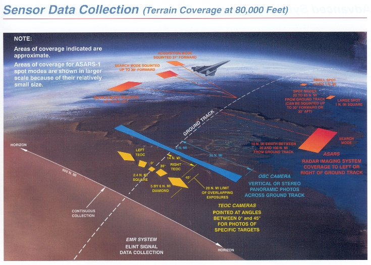
Itek also built versions of these cameras for use in the U-2 and SR-71 aircraft, in which they were called the OBC (Optical Bar Camera, named for the appearance of the field of regard on the ground).  These were first used in the 1960s and are still in use today.  Here is an Itek Optical Bar Camera that goes in the nose of an U-2:


Take a look at the big, wide blue bar under the airplane.  That's what a single frame of the camera shot.  It's huge.  I've heard that this "bar" looking frame was why they called it the optical bar camera.  However, the NRO's Hexagon documentation refers to the rotating optical assembly (what in many cameras is called the "Optical Tube Assembly") as the optical bar.


After a string of successful programs, requirements racheted up and tensions grew between NRO and CIA over the next program, Fulcrum.  Early on, Itek was contracting with both the NRO and the CIA on competing projects.  Itek pulled out of the CIA's project, and some combination of the NRO and the CIA took all their (government-owned) work and gave the job to Perkin-Elmer.  When the dust settled the project was renamed Hexagon.  Perkin-Elmer built the KH-9 Optical Bar Camera with their own design rather than Itek's, as they didn't think the Itek design would work.  Here is a look into the aperture of the KH-9 Optical Bar Camera.

The Itek OBCs in the U-2, SR-71, and Apollo spacecraft all had a rotating structure called the roller cage, which I suspect was fixed to the rotating camera.  The Perkin-Elmer design in the KH-9 deleted the roller cage and the rotating fold mirror inside it, and instead had a servo controlled twisting platen.

Here is a comparison of various optical bar cameras built up to 1971 (the launch of the first KH-9).

KA-80
(U-2/SR-71/Apollo)
(U-2/SR-71)(KH-9)
Focal length610 mm (24 inches)760 mm (30 inches)1524 mm (60 inches)
Aperture174 mm (f/3.5)218 mm (f/3.5?)508 mm (f/3.0)
Cross-track Field of View108 degrees140 degrees120 degrees
Film width127 mm (5 inches)127 mm (5 inches)168 mm (6.6 inches)
Film length2005 m (6500 feet)3200 m (10500 feet)70,000 m (230,000 feet)
Format114 x 1073 mm114 x 1857 mm155 x 3190 mm
Film resolution3.7 micron3.7 micron1000:1 contrast: 3.7 micron
1.6:1 contrast: 7.4 microns
Depth of focus+/- 13 microns+/- 13 microns+/- 11 microns
Format resolution31k x 290k = 9 Gpix31k x 502k = 15 Gpix42k x 862k = 36 Gpix
Frames1650164021,000
Nominal Altitude24.4 km (80k feet)24.4 km (80k feet)152 km (82 nm)
Center ground resolution14.8 cm11.9 cm37 cm
Swath67 km134 km555 km
In-track field of view, center4.55 km3.66 km15 km
Nominal overlap55%55%10% (each camera)
Area collected226k km2362k km22x 80m km2
Nominal ground velocity1000 m/s1000 m/s7,800 m/s
Cycle time2 sec1.65 sec1.73 sec
Film velocity at slit1.9 m/s2.9 m/s5.5 m/s
Maximum slit size7.62 mm12? mm22? mm
Max exposure time4 ms4? ms4? ms

Take a look at the area collected by the KH-9.  The Soviet Union was a big place: 20m km2.  Each of the four film re-entry capsules could return the entire USSR, in stereo, with plenty of side overlap and margin for images fouled by clouds.  Typically they chose to take more frames with smaller swaths (90 degrees or 60 degrees) to get higher average resolution, which brought down the total take somewhat to around 60 million km2.

My resolution numbers up there are slightly inflated.  The film used could only eke out 130 lp/mm when given the maximum possible amount of contrast, such as would be seen at a shadow line.  For finding something like paint on a road they were about half that.  Pixellated sensors have a much more drastic cliff, of course.  So the e.g. KH-9 resolution above might be compared to anything like a 20 to 30 gigapixel camera today.  I'll note that I don't have any of those to suggest.

There are two big concepts here that I think are important.  The first is the mechanical and logistical difficulties of using film.  Below I've spelled out some of the details.  The second is that despite these headaches, until very recently, film has been superior in many ways to electronic sensors for massive survey work.

The basic problems with using film stem from the fact that the sensor surface is a thin, pliable, moving, relatively inexpensive object that has to be held within the camera with very high precision.  There must have been several problems associated with getting the film aligned within +/- 11 microns of the lens's focal plane. Among other things, the machines resemble Van de Graf generators, and so the film is subject to static electricity buildup and discharges, along with heating that tends to make it even more pliable and sticky.  To reduce the static buildup, many of these cameras slid the film over surfaces with hundreds of pores lifting the film with pressurized air.

I think the Itek designs spun the entire optical assembly at a constant rate.  The entire spinning optical assembly is inside a gimbal which rocks back and forth 1.6 degrees in each cycle.  The rocking motion accomplishes forward motion compensation, so that the sweep of the slit across the ground is orthogonal to the direction of flight.  This compensation ensures that the motion of the image on the film moves almost exactly with the film, and there is no blurring in the direction of flight during longer exposures.  This rocking motion must have required fairly large torques, and I'm sure this is one of the things that the Perkin-Elmer folks balked at when considering the Itek design in space.  Note that a constantly rotating camera sweeps at the outer edges faster than at the center, so the forward motion compensation probably had to vary it's rate of rocking as it went to compensate.


Here is a diagram which shows how the film was wrapped around the roller cage in the Itek designs.  As the optical assembly (including the roller cage) twists counterclockwise, the film is transported clockwise.

However, even with a constant spin rate, the film does not transport at a constant rate.  For instance, in the SR-71 OBC, a frame is exposed for 640 ms, during which time the film rips around the roller cage at 2.9 meters per second (that's what the rollers see).  For the next second, the film advances at just 1 meter per second, so that the frame boundary going across the top of the roller cage can meet up with the slit going around the bottom.  Because of the speed change, many of the freewheeling rollers on the roller cage will contact unexposed film coming from the framing roller with a tangential speed difference of 1.9 meters per second.  As each freewheeling roller changes speed to match the film, it seems to me it would tend to scuff the film.  I'm sure they made sure to make those rollers as lightweight as possible to reduce their rotational momentum.

Note the unlabeled slit after the second mirror right next to the film wrapped around the roller cage.  Only the portion of the film after this in the optical chain has light on it, so this is the only spot that must be held accurately.  I don't really know how it was done, since every moving belt of material that I've even seen has vibrated.  They may have had a glass reseau plate that the film slid across.  Sliding film across glass at 2.9 meters per second seems like an excellent way to scratch one or both.  I have no evidence for it yet, but this seems like a good application for the compressed air film handling scheme.

The Itek forward motion compensation gimbal also took out airplane pitch motions.  Airplane roll motions were taken out by varying the optical tube roll rate.  That's easy enough (it doesn't require torque), but the film rate supplied to the roller cage assembly in the back also had to change to match.

That last diagram gives a pretty good clue to another challenge in this design -- film curvature.  Although I've not found any labelled dimensions, it looks like the roller cage in the Itek designs was about 300 mm in diameter.  The design of the roller cage really had me puzzled for a while, because the film transport path is cylindrical, but the film being exposed by the slit has to be flat.  I finally figured it out when I took a good look at this photo of the Apollo OBC (also made by Itek):


The roller cage is a cylindrical cage of ROLLERS!  Duh!  As the film passes between the rollers, it's locally flat, and that's how they keep the film surface matched to the lens focal plane.  Here's a 5x blowup of the roller cage in the picture above.  It looks like the rollers are packed together as close as they can get in order to minimize the polygonal variation in film distance from the center of roller cage rotation.  I think this variation leads to a (small) variation in film speed at the exposure site.
There should be a spot in the roller cage where there aren't any rollers, and the film becomes planar for a while.  This spot would be over the exposure slit.  In the Apollo OBC pictured here, the gap between the rollers must be at least 7.6mm, and given the orientation of the lens at the top it should be on the back side of the roller cage that we don't see here.


The film is pulled taut around the stuttering, bucking and twisting roller cage with an assembly that looks like the following.  During the exposure film is pulled around the roller cage at 5.7 meters/second.  Here's the film path:
If the tension on the film is too small, small irregularities in it's "set" curvature will make it lift off as it goes around the roller cage, and small patches of the film will lift away from the cage.  With a +/- 11 micron depth of focus, it doesn't take much lift off to make a problem.  If the tension is too high, the film will wrinkle longitudinally.


The Perkin-Elmer design did not have the roller cage or the gimbal.  Instead, they had a twisting platen assembly at the focal plane.  This would twist back and forth through 130 degrees as the optical bar rotated through 360 degrees.  The two were nearly locked together through the 120 degrees of rotation that were used for exposure.


Because the Perkin-Elmer design has no rocker gimbal doing forward motion compensation, and the optical assemblies rotate at constant speed, the sweep is faster at the edges than in the center, and the area swept in each frame is slightly S shaped.  They may have splayed the roll axes of the optical bars to get first order forward motion compensation, but this doesn't change the S shape.  To keep the image from smearing across the film, the KH-11 has to keep the slit perpendicular to the motion of the slit across the ground, accounting for the changing sweep rate versus spacecraft velocity, as well as the rotation of the Earth, which is 6% of the spacecraft velocity at the equator.

This is why the twisting platen in the KH-11 is servo locked to the twisting optical assembly.  They have to vary the relative twist of the two a little bit to keep the projected slit perpendicular to it's projected motion.

After the picture was shot the film sat around for a month in a temperature and humidity controlled environment, and then was dropped, recovered, and developed.  There was a lot of opportunity for the film to shrink differentially.  All the mechanical twisting, as well as film shrinkage, must have made photogrammetry a nightmare.

The Sunny 16 rule says that you can properly expose ISO 100 film in bright daylight conditions with a f/16 lens with a 10 ms exposure.  The KH-9 used mostly monochrome Kodak 1414, which has an Aerial Film Speed of 15, which I think is equivalent to ISO 38.  In full sun a 1 ms exposure at f/3 would have worked fine.  On the Apollo OBC that corresponds to a 1.9mm wide slit.  They did have exposure control hardware, and it looks like they could exposure for two stops dimmer than full sun.  They might have also stopped down from that, in order to avoid blowouts over ice.


At this point, I'm sure those of you who have worked with digital sensors are feeling pretty smug.  But consider how wonderful film was for capturing and returning large amounts of imagery.

Each of the four re-entry vehicles on the KH-9 would bring back 5,000 36 gigapixel images.  If somehow compressed to 1 bit per pixel, that would be about 20 terabytes.  These days that's about 10 hard disks, and would take about three months to downlink at a constant 25 megabits per second.  Since they were returning these re-entry vehicles every few months, a modern downlink is only barely adequate.  It has only been in the last 10 years or so that disk drive capacities have become high enough to fit the data into the payload of one of those re-entry vehicles -- 30 years after the KH-9 was originally deployed.

In 1971, the area of film actively integrating photons in the KH-9 was 155 mm x 15 mm.  The largest, fastest TDI CCD sensors commercially available in 2013 are 64 mm x 1.3 mm.  The pixels on these are 5.2 microns rather than 3.7 as on film.  The smaller integrating length (1.3 mm versus 22 mm) gives a maximum exposure time of  240 microseconds, which is smaller than the 2 milliseconds we would prefer.  155 mm x 10 mm CCDs with 3.7 micron pixels are not commercially available, but could probably be custom made.

Another issue would be the readout rate.  A fast TDI in 2013 reads out lines at 90 KHz.  The KH-9 was exposing film in the roller cage at 5.5 meters/second, which corresponds to a line readout rate of 1.5 MHz.  This could be achieved with a custom built TDI sensor maybe 5 years ago.  It would require 1300 ADCs running at 45 MHz, which would burn a lot of power.  This might be possible with interesting packaging.

The capture rate of the KH-9 was so enormous it completely overwhelmed the ability of the photointerpreters at the CIA to examine the photographs. It's only recently that computers have gotten large enough to store and process imagery at this volume, and it's not at all clear that anyone has yet developed algorithms to find the "unknown unknowns" in a bunch of raw imagery.  I think they call this "uncued image search".

To my knowledge the U.S. never again fielded a spysat with the ability to survey major portions of the earth at high resolution.  Later Keyhole satellites appear to have concentrated more on taking valuable single shots at higher resolution (7 cm GSD), and on having the orbital maneuverability to get those shots.  I think the intelligence folks lost interest in survey satellites when it became clear that they couldn't take advantage of the comprehensive coverage which was their primary feature.  It's kind of ironic that the very problem that Itek was founded to solve (managing the huge volume of survey photography) ended up being a major reason why satellites with survey capacity made possible by Itek's cameras faded away.  It's fascinating for me to see what has become of this problem.

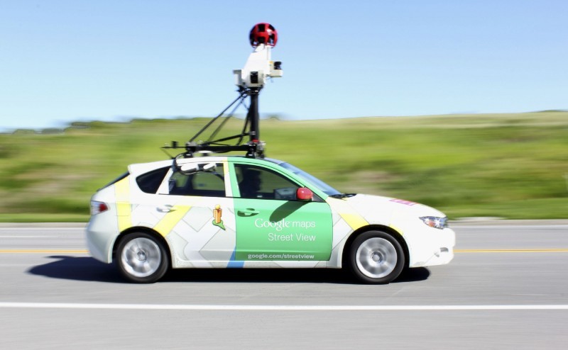
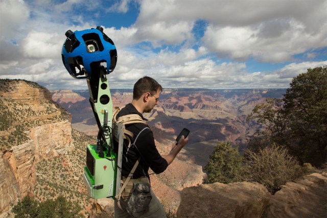
Brian McClendon is on record as saying that Google has 5 million miles and 20 petabytes of Street View imagery.  That's the processed imagery, not the raw take.  The KH-9 raw take that overwhelmed the CIA photointerpreter capacity 30 years ago was less than 1% of what Google Street View shot.  Unlike the KH-9 imagery, most of which I suspect has never been looked at, every one of the Street View panoramas has been seen by a real user.  And Google is hardly the only organization using Big Data like this.  The consumption problem that the CIA and NRO never solved has been utterly crushed by organizations with entirely different goals.  (Granted, uncued search remains unsolved.)

Now that Big Data has caught up with the photo throughput of digital satellites, it's fun to think about what could be built with modern technologies.  But that's probably best saved for another post.

Tuesday, March 19, 2013

R7 baffle being laser cut


Check it out!  This is the baffle for the R7 StreetView camera.  The final apertures are being cut with a laser.  These apertures have to line up with the view cone of the cameras fairly tightly, in order to clip off a ghost reflection in the lens that I missed during optical design.  The ghost only hits the sensor when the sun is in a 5 degree wide band just outside the field of view.  I suspect it's a fairly complex internal reflection path, since a simple double bounce ghost ought to sweep through the center of the lens as the sun does.

I had the idea of welding the whole baffle together and then as a final operation cutting the apertures, with the hope that the metal would stop moving around once we'd cut smaller apertures and finished welding.  It didn't really work out perfectly.  There was a fair bit of tolerance stackup between the internal lenses and this external baffle.  Also, the baffle mounted to 8 screws, and those 8 points would tend to get significantly out of alignment, so that the baffle shape that you ended up with depended on what order you tightened the screws.  As a result we had to open up some extra margin on the baffle openings.  I know for a fact that the sun can leak into the corners.  After a quick check, I can't find any examples of the ghost, though, so the baffle is doing a decent job.

R7 at work:


R7 at play.  Hi Ryan!  Note the ears on top.  Those are the twin GPS antennae... the way I intended all R7s to be.


Friday, February 15, 2013

Mixing Clouds

First, let me recommend a great book: Clouds in a Glass of Beer: Simple Experiments in Atmospheric Physics: Craig F. Bohren: 9780486417387: Amazon.com: Books  It's short and is composed of many short chapters, each with an experiment and an explanation.  Chapter 5, mixing clouds, has always bugged me, and in response to a Quora question I finally did the math on the white stuff coming out of a kettle on the stove.

The clear stuff coming out of your kettle spout is 100% vaporized water.  (I'll sidestep pedantic discussions of the meanings of "steam" and "water vapor".)  It quickly entrains the cooler air around the kettle and mixes with it, forming a mixing cloud, which you can see and most folks refer to as "steam".

The mixing cloud forms because the relationship between the vapor pressure of water and temperature is not linear but rather curved.  It's the red set of dots above.  This is really important, so take a moment with the idea.  As the temperature of the water in the kettle rises from 20 C (room temperature) to 100 C (boiling), the pressure component of the air/vapor mix above it due to the vapor rises from something quite tiny to 1 bar (standard atmospheric pressure).

Now let's dilute that ejected 100% water vapor with some dry air at 20 C.  The mixed result is cooler than 100 C and has a lower vapor pressure than 1 bar (because not all the stuff is water vapor any more).  Once you've accounted for the different heat capacities of water vapor and water, and the thermal expansion or contraction of the constituents, you get the blue curve above.  You read the curve like so: if I mix some amount of 20 C dry air into some 100 C water vapor, so that the result is 60 C, then it's partial pressure of water vapor is 0.29 bar.  At least, that would be the partial pressure if all the water was in vapor form.

The really neat thing here is that the blue curve is ABOVE the red curve all the way down to 26 degrees C, which happens to correspond to 95.8% dry air and 4.2% water vapor.  At any mixing ratio between this and 100% water vapor, there will be more water in the mixing cloud than can be in vapor phase, and some will be in the form of very tiny (micron) water droplets.  However, once the mixing cloud is sufficiently diluted with dry air, there will be less water vapor in it than the maximum that can be in vapor phase, and all those tiny droplets with their huge surface air to volume ratio will immediately evaporate.

What this means is that the mixing cloud grows to 23 times bigger than the pure water vapor expelled from the kettle before it disappears.

Wednesday, January 30, 2013

Thousands of drones


Someone recently asked me if aerial survey could be accomplished with a swarm of tiny drone aircraft.  Imagine foot-long planes made of styrofoam, carrying the camera, IMU, and GPS of a cellphone, minus the display, with a far larger battery for propulsion.  How can this fail to be a cheaper way to survey large areas?

I've worked on a drone program before, but that was with a gas-powered UAV weighing 25 kg empty with a 2 kg payload and a range of around 1100 km over an 6 hour flight, costing in excess of $50k.  Operational costs were expected to be dominated by the cost of crashing.  I can say confidently that these are not a cheap way to survey anything.

In researching this blog post, I learned about solar-electric RC airplanes, which are a completely different kettle of fish.  The Aphelion, above, was built for under $500 (materials only) in Professor Mark Drela's MIT lab, and can fly at 5-6 m/s for as long as the sun is 6.5 degrees above the horizon, which is something like 8 to 12 hours a day.  That puts the daily range around 150 km.

Crucially, the whole airplane weighs 1300 grams distributed over a 3.3 meter wingspan.  My guess is that a Cessna might survive an in-flight impact with one of these, and maybe even something a bit heavier.

A survey drone version would be ruggedized for e.g. 1000 flights MTBF, would carry a 200 g camera payload and a 50g battery, would fly at 12 m/s, and cover 300 km during a day's flight.  Higher speeds lead to more coverage and better survivability in higher winds, but also smaller wings and less solar power.  The battery allows flight with intermittent solar coverage, due to clouds and building blockages.

This range is not great.  If a drone maintained 10 m/s from 9AM to 3PM, it would cover 216 km.  For comparison, a King Air B200, which is something of a standard twin-turboprop airplane for aerial survey, flies at 140 to 150 m/s and can cover 1700 km in a morning.

These drones are going to require an ultralight camera -- basically a cellphone camera.  The camera scales surprisingly well, primarily because you are comparing cellphone sensors to huge custom CCDs used in e.g. Leica ADS80 aerial cameras, and of course the cellphone sensors are far better because they have far more engineering investment.  Nowadays I would use an Aptina MT9F002 14-megapixel sensor with a 10mm lens, which will deliver 2 inch resolution from 1000 feet up.  This will deliver a swath of over 200 meters.  Because the drone will bounce around a fair bit, we'll need a very generous overlap between the imagery captured in one flight line and the next, so the flight pitch will be something like 150 meters.  For comparison, an ADS80 camera in a B200 flies with a 1 kilometer flight pitch when shooting this resolution.

Due to the close range and excellent sensor there is no need for a gimbal for the drone camera.  I'd use a 400 microsecond exposure time.  Combine that with the 140 microradian pixel field of view, and the camera can tolerate rolls and pitches of 25 to 50 degrees per second without excessive motion blur.  I think even a little drone with very low wing loading can deliver that most of the time.  If we shoot 94% forward overlap between frames (1 frame per second), which is possible because we are going so slowly, then if we lose a few shots due to motion blur we can afford to just drop them.  We'll collect about 100 GB of data in 6 hours at that frame rate, which will be storable on a microSD card next year.

Now we come to the very bad news for this idea.  The combination of low speed and small flight pitch means that we'll need something like 100 drones to replace a ADS80 in a B200.  If you talk to R/C folks, you will find that they spend at least as much time fixing their aircraft as they do flying them.  So those 100 drones are going to require an army of people to launch, recover, and repair them.

The bottom line is that using drones instead of manned aircraft still seems like a bad idea... if you can use a manned aircraft.  But here is how survey drones might turn out to be a really wonderful idea:  If you can make the drone light enough that it just won't hurt anyone when it crashes, then you might be able to get permission to fly down city streets.  THAT would rock, because you'd simultaneously solve a bunch of problems that a bunch of folks (Nokia/Navteq, TomTom/TeleAltas, Google) are spending hundreds of millions of dollars a year on today:
  • You would be collecting street level imagery without having to wait for traffic.  Much, much faster.
  • The native perspective of the cameras would be the one that people actually want.  This is just my intuition, but my sense from working on Street View is that it was too damn slow and difficult to navigate.  I think people want a raised perspective, but just not raised too much.
  • You would be collecting the sides of buildings at high resolution.  Right now there is a major gap between street-level resolution (Google's Street View is 3mm resolution) and aerial resolution (Google's 45 degree view is 100mm resolution).  That gap means that the sides of buildings don't match up well, which is a problem if, like Apple and Google, you want to deliver great looking 3D models of buildings.
  • Aerial obliques don't actually work in places like New York because the buildings are too tall compared to the street width.  However, if you fly between the buildings, this is no longer a problem!  This is a major issue now that over half the world's population (likely the wealthier half) live in cities.
I think it's a big stretch to imagine getting permission to fly your UAVs down city streets, and technically it would be a big challenge just to plan the routes... you'd probably end up needing to survey the city from high altitude first.  It sure is fun to think about, though.

Friday, December 14, 2012

Cloud + Local imagery storage

The Department of Homeland Security has said that it wants imagery delivered in the cloud. Several counties and states have expressed the same desire. Amazon S3 prices are quite reasonable for final imagery data delivered, especially compared to the outrageous prices that imagery vendors have been charging for what amounts to a well-backed-up on-site web server with static content. I've heard of hundreds of thousands of dollars for serving tens of terabytes.

Everyone wants the reliability, size, and performance scalability of cloud storage. No matter how popular your imagery becomes (e.g. you happen to have the only pre-Sandy imagery of Ocean City), and no matter how crappy your local internet link happens to be, folks all around the world can see your imagery. And many customers are more confident in Amazon or Google backups than their local IT backups.

But everyone also wants the reliability of local storage. E911 services have to stay up even when the internet connection goes down. So they need their own local storage. This also helps avoid some big bandwidth bills on the one site you know is going to hammer the server all the time.

So really, imagery customers want their data in both places. But that presents a small problem because you do want to ensure that the data on both stores is the same. This is the cache consistency problem. If you have many writers frequently updating your data and need transaction semantics, this problem forces an expensive solution. But, if like most imagery consumers you have an imagery database which is updated every couple of months by one of a few vendors, with no contention and no need for transaction semantics, then you don't need an expensive solution.

NetApp has a solution for this problem which involves TWO seriously expensive pieces of NetApp hardware, one at the customer site and one in a solo site with a fat pipe to Amazon. The two NetApp machines keep their data stores synchronized, and Amazon's elastic cloud accesses data stored at the colo over the fat pipe. This is... not actually cloud storage. This is really the kind of expensive shoehorned solution that probably pisses off customers more than me because they have to write the checks.

The right answer (for infrequently-updated imagery) is probably a few local servers with separate UPSes running Ceph and something like rsync to keep updates synchronized to S3. Clients in the call center fail over from the local servers to S3, clients outside the call center just use S3 directly.

I feel sure there must be some Linux vendor who would be happy to ship the Nth system they've build to do exactly this, for a reasonable markup to the underlying hardware.

Wednesday, December 05, 2012

Dragonfly Eyes - the Wonders of Low Resolution


Continuing with the recent theme of analyzing both natural and man made cameras, I thought I'd analyze an insect eye in this post.  In previous posts I've analyzed a gigapixel airborne security video camera and the eye of a raptor.  I'm working on analyses of the F-35's Distributed Aperture System as well as a really gigantic film camera for future posts.

The picture above is of a blue-spotted Hawker dragonfly.  This creature apparently catches its prey in midflight, so it's supposed to have big, high resolution eyes.  According to John Patterson in this Discover magazine article, it has 28,000 lenses in each eye.  Judging from the picture, those eyes are probably covering half of the possible 4*pi solid angle, so each tiny lens is covering a solid angle of 112 microsteradians.  That would be Low Resolution to my mind.  Critters like spiders and grasshoppers, with even smaller eyes, must be commensurately worse.

To give some context, a human in bright light has a pixel field of view of 25 nanosteradians.  You can see across your yard (70 feet) what the dragonfly can see from 1 foot.  If it is going after an 8mm long house fly, it needs to close within 80 cm in order to get a full pixel on the target.  At that range the house fly can probably hear the dragonfly, although I haven't analyzed that and insect hearing might also be much worse than human hearing.  This dragonfly is not a long-range hunter like a bird, but rather an opportunist.  I very much doubt it can pull off a high-relative-speed attack like a Peregrine falcon, which requires good angular resolution and gimbal stabilization.

Interestingly, the creature collects about the same amount of light per pixel that the human eye does.  The entire creature is about 70mm long.  Judging from the picture below, the eyes are probably 10 mm across.  That means those little lenses are 53 microns across.  On a bright day outside, your human pupils constrict to 3 mm, 55 times larger.  But since the dragonfly's pixel field of view is 70 times bigger, it actually receives about 50% more light per pixel than you do.
I used to be concerned that the tiny dragonfly lenses would cause diffraction blurring.  Supposing for a moment that they look at green light, their Rayleigh criterion is about 12 milliradians, nicely matched to their pixel angular field of view of 10.5 milliradians.  If the effective pupil of each lens is substantially smaller than the allotted space (low fill factor), then the dragonfly would have to use a shorter wavelength to avoid diffraction problems.  It doesn't look like a big problem.

I don't think the dragonfly has to stabilize the scenery with it's neck.  A dragonfly flying at 1 meter/second sees scenery 50 cm away to the side going by at 2 radians/second.  To get less than 3 pixels of motion smear, it would have to integrate the exposure for less than 15 milliseconds.  That's just a bit quick, so the creature probably sees some motion blur to the side, but not so much in front of it, since there is considerably less angular motion in the direction of flight.


Monday, September 03, 2012

Red Rocks!

Here's an explanation from RED about why high frame rate video is a good thing.  They are right, and this is a great explanation with really impressive examples.

Monday, August 27, 2012

ARGUS-IS

Here's an exotic high flying camera: ARGUS-IS.  I've been trying to figure what these folks have been up to for years, and today I found an SPIE paper they published on the thing.  What follows is a summary and my guesses for some of the undocumented details. [Updated 30-Jan-2013, to incorporate new info from a Nova documentary and a closer reading of the SPIE paper.]
Vexcel Ultracams also use four cameras
with interleaved sensors


  • It looks like BAE is the main contractor.  They've subcontracted some of the software, probably the land station stuff, to ObjectVideo.  BAE employs Yiannis Antoniades, who appears to be the main system architect.  The lenses were subcontracted out to yet another unnamed vendor, and I suspect the electronics were too.
  • Field of view: 62 degrees.  Implied by altitude 6 km and object diameter 7.2 km.
  • Image sensor: 4 cameras, each has 92 Aptina MT9P031 5 megapixel sensors.  The paper has a typo claiming MT9P301, but no such sensor exists.  The MT9P031 is a nice sensor, we used it on the R5 and R7 Street View cameras.
    • 15 frame/second rate, 96 MHz pixel clock, 5 megapixels, 2592 x 1944.
    • It's easy to interface with, has high performance (quantum efficiency over 30%, 4 electrons readout noise, 7000 electrons well capacity), and is (or was) easy to buy from Digikey.  (Try getting a Sony or Omnivision sensor in small quantities.)
  • Focal length: 85mm.  Implied by 2.2 micron pixel, altitude of 6 km, GSD of 15 cm.  Focal plane diameter is 102mm.  The lens must resolve about 1.7 gigapixels.  I must say that two separate calculations suggest that the focal length is actually 88mm, but I don't believe it, since they would have negative sensor overlap if they did that.
  • F/#: 3.5 to 4.  There is talk of upgrading this system to 3.7 gigapixels, probably by upgrading the sensor to the Aptina MT9J003.  An f/4.0 lens has an Airy disk diameter of 5.3 microns, and it's probably okay for the pixels to be 2.2 microns.  But 1.66 micron pixels won't get much more information from an f/4.0 lens.  So, either the lens is already faster than f/4.0, or they are going to upgrade the lens as well as the sensors.
  • The reason to use four cameras is the same as the Vexcel Ultracam XP: the array of sensors on the focal plane cannot cover the entire field of view of the lens.  So, instead, they use a rectangular array of sensors, spaced closely enough so that the gaps between their active areas are smaller than the active areas.  By the way guys (Vexcel and ObjectVideo), you don't need four cameras to do this problem, it can be solved with three (the patent just expired on 15-Jul-2012).  You will still need to mount bare die.
  • The four cameras are pointed in exactly the same direction.  Offsetting the lenses by one sensor's width reduces the required lens field of view by 2.86 degrees, to about 59 degrees.  That's not much help.  And, you have to deal with the nominal distortion between the lenses.  Lining up the optical axes means the nominal distortion has no effect on alignment between sensors, which I'm sure is a relief.
  • The sensor pattern shown in the paper has 105 sensors per camera, and at one point they mention 398 total sensors.  The first may be an earlier configuration and the latter is probably a typo.  I think the correct number is 92 sensors per camera, 368 total.  So I think the actual pattern is a 12x9 rectangular grid with 11.33mm x 8.50mm centers.  16 corner sensors (but not 4 in each corner) are missing from the 9x12=108 rectangle, to get to 92 sensors per focal plane.  The smallest package that those sensors come in is 10mm x 10mm, which won't fit on the 8.5mm center-to-center spacing, so that implies they are mounting bare die to the focal plane structure.
  • They are carefully timing the rolling shutters of the sensors so that all the rolling shutters in each row are synchronized, and each row starts it's shutter right as the previous row finishes.  This is important, because otherwise when the camera rotates around the optical axis they will get coverage gaps on the ground.  I think there is a prior version of this camera called Gorgon Stare which didn't get this rolling shutter synchronization right, because there are reports of "floating black triangles" in the imagery, which is consistent with what you would see on the outside of the turn if all the rolling shutters were fired simultaneously while the camera was rotating.  Even so, I'm disappointed that the section on electronics doesn't mention how they globally synchronize those rolling shutters, which can be an irritatingly difficult problem.
  • They are storing some of the data to laptop disk drives with 160 GB of storage.  It appears they may have 32 of these drives, in which case they've got enough space to potentially store the entire video stream, but only with very lossy video compression.  The design presented has only JPEG2000 (not video) compression, which will be good for stepping through the frames, but the compression ratio will be bulky enough that there is no way they are storing all the video.
  • They have 184 FPGAs at the focal plane for local sensor control, timestamping, and serialization of the data onto 3.3 Gb/s fiber optics.  Supposedly the 3.3 Gb/s SerDes is on the FPGA, which sounds like a Virtex-5 20T.  But something is odd here, because having the SerDes on the FPGA forces them to choose a fairly beefy FPGA, but then they hardly do anything with it: the document even suggests that multiplexing the two sensor data streams, as well as serialization of those streams, happens outside the FPGA (another typo?).  So what's left for a Virtex-5 to do with a pair of sensors?  For comparison, I paired one Spartan-3 3400A with each sensor in R7, and we were able to handle 15 fps compression as well as storage to and simultaneous retrieval from 32 GB of SLC flash, in that little FPGA.  Maybe the SerDes is on some other device, and the FPGA is more of a PLD.
  • The data flows over fiber optics to a pile of 32 6U single board computers, each of which has two mezzanine cards with a Virtex 5 FPGA and two JPEG2000 compressors on it.
Now here's my critique of this system design:
  • They pushed a lot of complexity into the lens.
    • It's a wide angle, telecentric lens.  Telecentric means the chief rays coming out the back, heading to the focal plane, are going straight back, even at the edges of the focal plane.  Said another way, when you look in the lens from the back, the bright exit pupil that you see appears to be at infinity.  Bending the light around to do that requires extra elements.  This looks a lot like the lenses used on the Leica ADS40/ADS80, which are also wide angle telecentric designs.  The Leica design is forced into a wide angle telecentric because they want consistent colors across the focal plane, and they use dichroic filters to make their colors.  The ARGUS-IS doesn't need consistent color and doesn't use dichroics... they ended up with a telecentric lens because their focal plane is flat.  More on that below.
    • The focal lengths and distortions between the four lenses must be matched very, very closely.  The usual specification for a lens focal length is +/- 1% of nominal.  If the ARGUS-IS lens were built like that, the image registration at the edge of field would vary by +/- 500 microns.  If my guesses are right, the ARGUS-IS focal plane appears to have 35x50 microns of overlap, so the focal lengths of the four lenses will have to match to within +/- 0.07%.  Wow.
    • "The lenses are athermalized through the choice of glasses and barrel materials to maintain optical resolution and focus over the operational temperature range."  Uh, sure.  The R7 StreetView rosette has 15 5 megapixel cameras.  Those lenses are athermalized over a 40 C temperature range, and it was easy as pie.  We just told Zemax a few temperature points, assumed an isothermal aluminum barrel, and a small tweak to the design got us there.  But those pixels have a field of view of 430 microradians, compared to the pixels behind the ARGUS-IS lens, which have a 25 microradian PFOV.  MIL-STD-810G, test 520.3, specifies -40 C to 54 C as a typical operating temperature range for an aircraft equipment bay.  If they had anything like this temperature range specified, I would guess that this athermalization requirement (nearly 100 degrees!) came close to sinking the project.  The paper mentions environmental control within the payload, so hopefully things aren't as bad as MIL-STD-810G.
    • The lenses have to be pressure compensated somehow, because the index of refraction of air changes significantly at lower pressures.  This is really hard, since glasses, being less compressible than air, don't change their refractive indices as fast as air.  I have no particularly good ideas how to do it, other than to relax the other requirements so that the lens guys have a fighting chance with this one.  Maybe the camera can be specified to only focus properly over a restricted range of altitudes, like 4km to 8km.  (ARGUS-IR specifies 0 to 10km.  It's likely ARGUS-IS is the same, so no luck there.)  Or maybe everything behind their big flat window is pressurized.
  • They made what I think is a classic system design mistake: they used FPGAs to glue together a bunch of specialized components (SerDes, JPEG compressors, single board computers), instead of simply getting the job done inside the FPGAs themselves.  This stems from fear of the complexity of implementing things like compression.  I've seen other folks do exactly the same thing.  Oftentimes writing the interface to a off-the-shelf component, like a compressor or an encryption engine, is just as large as writing the equivalent functionality.  They mention that each Virtex-5 on the SBC has two 0.6 watt JPEG2000 chips attached.  It probably burns 200 mW just talking to those chips.  It seems to me that Virtex could probably do JPEG2000 on 80 Mpix/s in less than 1.4 watts.  Our Spartan-3 did DPCM on 90+ Mpix/s, along with a number of other things, all in less than 1 watt.
  • I think I remember reading that the original RFP for this system had the idea that it would store all the video shot while airborne, and allow the folks on the ground to peruse forward and backward in time.  This is totally achievable, but not with limited power using an array of single-board PCs.
Let me explain how they ended up with a telecentric lens.  A natural 85mm focal length lens would have an exit pupil 85mm from the center of the focal plane.  Combine that with a flat focal plane and sensors that accept an f/1.8 beam cone (and no offset microlenses), and you get something like the following picture.  The rectangle on the left is the lens, looking from the side.  The left face of the right rectangle is the focal plane.  The big triangle is the light cone from the exit pupil to a point at the edge of the focal plane, and the little triangle is the light cone that the sensor accepts.  Note that the sensor won't accept the light from the exit pupil -- that's bad.


There are two ways to fix this problem.  One way is to make the lens telecentric, which pushes the exit pupil infinitely far away from the focal plane.  If you do that, the light cone from the exit pupil arrives everywhere with it's chief ray (center of the light cone) orthogonal to the focal plane.  This is what ARGUS-IS and ADS-80 do.

The other way is to curve the focal plane (and rename it a Petzval surface to avoid the oxymoron of a curved focal plane).  Your retina is curved behind the lens in your eye, for example.  Cellphone camera designers are now looking at curving their focal planes, but it's pretty hard with one piece of silicon.  The focal plane array in ARGUS-IS is made of many small sensors, so it can be piecewise curved.  The sensors are 7.12 mm diagonally, and the sag of a 85 mm radius sphere across 7.12 mm is 74 microns.  The +/- 9 micron focus budget won't allow that, so curving the ARGUS-IS focal plane isn't going to allow a natural exit pupil.  The best you can do is curve the focal plane with a radius of 360 mm, getting 3.6 mm of sag, and push the exit pupil out to about 180 mm.  It's generally going to be easier to design and build a lens with an exit pupil at 2x focal length rather than telecentric, but I don't know how much easier.  Anyway, the result looks like this:
As I said, the ARGUS-IS designers didn't bother with this, but instead left the focal plane flat and pushed the exit pupil to infinity.  It's a solution, but it's not the one I would have chosen.

Here's what I would have done to respond to the original RFP at the time.  Note that I've given this about two hours' thought, so I might be off a bit:
  • I'd have the lenses and sensors sitting inside an airtight can with a thermoelectric cooler to a heat sink with a variable speed fan, and I'd use that control to hold the can interior to between 30 and 40 C (toward the top of the temperature range), or maybe even tighter.  I might put a heater on the inside of the window with a thermostat to keep the inside surface isothermal to the lens.  I know, you're thinking that a thermoelectric cooler is horribly inefficient, but they pump 3 watts for every watt consumed when you are pumping heat across a level.  The reason for the thermoelectric heat pump isn't to get the sensor cold, it's to get tight control.  The sensors burn about 600 mW each, so I'm pumping 250 watts outs with maybe 100 watts.
  • I'd use a few more sensors and get the sensor overlap up to 0.25mm, which means +/-0.5% focal length is acceptable.  I designed R5 and R7 with too little overlap between sensors and regretted it when we went to volume production.  (See Jason, you were right, I was wrong, and I've learned.)
  • Focal plane is 9 x 13 sensors on 10.9 x 8.1 mm centers.  Total diameter: 105mm.  This adds 32 sensors, so we're up to an even 400 sensors.
  • Exiting the back of the fine gimbal would be something like 100 flex circuits carrying the signals from the sensors.
  • Hook up each sensor to a Spartan-3A 3400.  Nowadays I'd use an Aptina AR0330 connected to a Spartan-6, but back then the MT9P001 and Spartan-3A was a good choice.
  • I'd have each FPGA connected directly to 32GB of SLC flash in 8 TSOPs, and a 32-bit LPDDR DRAM, just like we did in R7.  That's 5 bytes per pixel of memory bandwidth, which is plenty for video compression.
  • I'd connect a bunch of those FPGAs, let's say 8, to another FPGA which connects to gigabit ethernet, all on one board, just like we did in R7.  This is a low power way to get connectivity to everything.  I'd need 12 of those boards per focal plane.  This all goes in the gimbal.  The 48 boards, and their power and timing control are mounted to the coarse gimbal, and the lenses and sensors are mounted to the fine gimbal.
  • Since this is a military project, and goes on a helicopter, I would invoke my fear of connectors and vibration, and I'd have all 9 FPGAs, plus the 8 sensors, mounted on a single rigid/flex circuit.  One end goes on the focal plane inside the fine gimbal and the other goes on the coarse gimbal, and in between it's flexible.
  • I'd connect all 52 boards together with a backplane that included a gigabit ethernet switch.  No cables -- all the gigE runs are on 50 ohm differential pairs on the board.  I'd run a single shielded CAT-6 to the chopper's avionics bay.  No fiber optics.  They're really neat, but power hungry.  Maybe you are thinking that I'll never get 274 megabits/second for the Common Data Link through that single gigE.  My experience is otherwise: FPGAs will happily run a gigE with minimum interpacket gap forever, without a hiccup.  Cheap gigE switches can switch fine at full rate but have problems when they fill their buffers.  These problems are fixed by having the FPGAs round-robin arbitrate between themselves with signals across that backplane.  Voila, no bandwidth problem.
  • The local FPGA does real time video compression directly into the flash.  The transmission compression target isn't all that incredible: 1 bit per pixel for video.  That gets 63 channels of 640x400x15 frames/sec into 274 Mb/s.  The flash should give 1 hour of storage at that rate.  If we want 10 hours of storage, that's 0.1 bits/pixel, which will require more serious video compression.  I think it's still doable in that FPGA, but it will be challenging.  In a modern Spartan-6 this is duck soup.
  • The computer tells the local FPGAs how to configure the sensors, and what bits of video to retrieve.  The FPGAs send the data to the computer, which gathers it up for the common data link and hands it off.
  • I'll make a guess of 2 watts per sensor+FPGA+flash, or 736 watts.  Add the central computer and switch and we're at 1 kilowatt.  Making the FPGAs work hard with 0.1 bit/pixel video compression might add another 400 watts, at most.
  • No SSDs, no RAID, no JPEG compression chips, no multiplexors, no fiber optic drivers, no high speed SerDes, no arrays of multicore X86 CPUs.  That's easily half the electronics complexity, gone.
UPDATE 25-Jan-2013: Nova ran a program on 23-Jan-2013 (Rise of the Drones) which talks about ARGUS-IS.  They present Yiannis Antoniades of BAE systems as the inventor, which suggests I have the relationship between BAE and ObjectVideo wrong in my description above.  They also say something stupid about a million terabytes of data per mission, which is BS: if the camera runs for 16 hours the 368 sensors generate 2,000 terabytes of raw data.

They also say that the ARGUS-IS stores the entire flight's worth of data.  I don't think they're doing that at 12 hertz, certainly not on 160 GB drives.  They've got 32 laptop drives in the system (one per single board computer).  If those store 300 GB apiece, that's 10 terabytes of total storage.  16 hours of storage would require 0.05 bits/pixel -- no way without actual video compression.  The JPEG2000 compressor chips are more likely to deliver at best 0.2 bits/pixel, which means they might be storing one of every four frames.

UPDATE 27-Jan-2013: An alert reader (thanks mgc!) sent in this article from the April/May 2011 edition of Science and Technology Review, which is the Lawrence Livermore National Laboratory's own magazine.  It has a bunch of helpful hints, including this non-color-balanced picture from ARGUS-IS which lets you see the 368 sensor array that they ended up with.  It is indeed a 24 x 18 array with 16 sensors missing from each corner, just as I had hypothesized.
The article mentions something else as well: the Persistics software appears to do some kind of super-resolution by combining information from multiple video frames of the same nearly static scene.  They didn't mention the other two big benefits of such a scheme: dynamic range improvement and noise reduction (hence better compression).  With software like this, the system can benefit from increasing the focal plane to 3.8 gigapixels by using the new sensor with 1.66 micron pixels.  As I said above, if the lens is f/3.5 to f/4.0 lens they won't get any more spatial frequency information out of it with the smaller pixels, but they will pick up phase information.  Combine that with some smart super-resolution software and they ought to be able to find smaller details.  Question though: why not just go to the MT9F002, which gives you 14 million 1.4 micron pixels?  This is a really nice, fast sensor -- I've used it myself.

The article also mentions 1000:1 video compression.  That's very good: for comparison, H.264 level 4 compresses 60 megapixels/second of HDTV into 20 megabits/second, which is 0.33 bits/pixel or 36:1 compression.  This isn't a great comparison, though, because Persistics runs on almost completely static content and H.264 has to deal with action movie sequences.  In any case, I think the Persistics compression is being used to archive ARGUS-IS flight data.  I don't think they are using this compression in the aircraft.

Monday, August 13, 2012

More vision at 360nm

I thought of two other consequences of birds, especially hawks, seeing ultraviolet light.

The first has to due with scattered light.  The nitrogen and oxygen molecules in the atmosphere act like little dipoles, scattering some of the light passing through.  The amount of light scattered increases as the fourth power of frequency (or inverse fourth power of wavelength).  The process is called Rayleigh scattering (yep, same guy as the last rule).

Because of that strong wavelength dependence, our blue-sensitive cones receive 3 times as much light scattered by nitrogen and oxygen as our red cones, and when we look up at a cloudless sky in the day, we see the sky is blue.  Here are the response curves for the three types of cones and the rods in human vision.  (That's right, you actually have four color vision, but you can only see blue-green (498nm) with your rods when it's too dim for your cones to see.)


But now imagine what a hawk sees.  It has another color channel at 360nm, which sees 6 times as much scattered light as red.  When looking up, the sky will appear more UV than blue.  But there is more to it than that.

Rayleigh scattering is not isotropic.  The dipoles scatter most strongly at right angles to the incoming light.  When you look up at the sky, the intensity of blue changes from near the sun to 90 degrees away.  It's a little hard to see because when looking up you also see Mie scattering which adds yellow light to the visible sky near the sun.  But when you look down, like a hawk does, Mie scattering isn't an issue (instead you have less air Rayleigh scattering and more ground signal).  The overall color gradient from Rayleigh scattering that a hawk sees looking down will be twice as strong as the color gradient we see, because the hawk sees in UV. In direct sunlight, the hawk has a measure of the sun's position whenever it is looking at the ground, even when there are no shadows to read.

The other consequence is axial chromatic aberration.  Most materials have dispersion, that is, they present a different index of refraction to different wavelengths of light.  One consequence of dispersion is that blue focusses in front of red (for lenses like the eye).  I used to think this was a bad thing.  But if your cones tend to absorb light of one color and pass light of the others, and your resolution is limited by the density of cones, a little chromatic aberration is a good thing, because it allows you to stack the UV cones in front of the blue cones in front of the green and red cones, and they all get light focussed from the same range.  I know that retinas have layered stacks of rods, cones, and ganglion cells, but I don't know that any animals, hawks in particular, have actually taken advantage of axial chromatic aberration to stack cones of different colors.  It's certainly something I'll be looking for now.

Sunday, August 12, 2012

Hawk eyed


The resolution of a good long-distance camera is limited by diffraction. The simple rule for this is the Rayleigh criterion:

Theta is the angular resolution, the smallest angular separation between two bright lines that can be differentiated by the system.

Lambda is the wavelength of light. You can see reds down at 700nm, and blues to 400nm. Interestingly, birds can see ultraviolet light at 360nm. The usual explanation for this is that some flowers have features only visible in ultraviolet, but I think raptors are using ultraviolet to improve their visual acuity.

D is the diameter of the pupil. Bigger pupils not only gather more light, but they also improve the diffraction limit of the optical system. The trouble with bigger pupils is that they make various optical aberrations, like spherical aberration, worse. These aberrations are typically minimized near the center of the optical axis and get much worse farther from the optical axis.  So a big pupil is good if you want a high-resolution fovea and are willing to settle for crummy resolution but good light gathering outside that fovea.  This is the tradeoff the human eye makes.

A human's eye has a pupil about 4mm across in bright light. According the Rayleigh criterion, human resolution at 550nm should be about 170 microradians. According to a Wikipedia article on the eye, humans can see up to 60 counts per degree, which corresponds to 290 microradians per line pair. That suggests the human eye is not diffraction limited, but rather limited by something else, such as a combination of focal length and the density of cone cells on the retina.

I wasn't able to find a good reference for the pupil diameter of a red-tailed hawk. Judging from various pictures, I'm guessing it could be smaller than a human pupil, since it appears that the hawk's eyeball is quite a bit smaller than the human eye (absolute scale). This doesn't seem good enough, since hawks are reputed to have fabulous vision. The first reference I found online suggested that hawks have visual acuity that's actually worse than humans.

Suppose that this last study was using paints that were undifferentiated in UV, in particular, around 360 nm. The researchers would not have noticed this. Suppose further that hawks are using 360 nm light for high acuity vision. The diffraction limit of a 4 mm aperture in 360 nm light is 110 microradians. This isn't 8 times better than human vision, but it is sufficient to distinguish two twigs 1 cm apart from 100 meters up.

Sunday, May 27, 2012

More on hot-rock geothermal


When you drill a hole in the ground and flush water or CO2 through it, you cool the rock you've drilled through.  The amount of heat energy that comes up from that hole depends on how much rock you can cool.  And that depends on how conductive and permeable the rock is.

To get a feel for how much energy we're used to getting out of a hole in the ground, let's consider another industry that gets energy out of drilling holes in the ground: oil wells in the United States.  Half of US oil production comes from wells producing over 118 barrels of oil per day (ftp://www.eia.doe.gov/pub/oil_gas/petrosystem/us_table.html).  That's about 6.6 megawatts of chemical energy, which can be converted into about 4 megawatts of electricity.  These wells typically run for 20 years.

Geothermal wells will have to produce similar amounts of energy or the cost of drilling the well will make them uneconomic.

To get 4 MW of electricity from rocks that you cool from, say, 220 C to 170 C, you first need about 16 megawatts of heat, since your heat source is cooler than an oil flame and the heat engine it runs will have a lower Carnot efficiency.  Over 20 years, that flow will cool about 100,000,000 cubic meters of rock 50 degrees C.  If your well is 1 kilometer deep, you need to have cooled a region about 350 meters in diameter around the well.  Geothermal on a scale large enough to make a difference will need thousands of these wells separated by 500 meters or more, but connected by hot steam pipelines to bring otherwise diffuse steam to turbines large enough to be cost effective.

If we are to lose at most 10 degrees C of temperature delta to conduction, the cracks in the rock that carry the flow of fluid cooling it must be separated by less than 25 meters.  If there is significant flow restriction in those cracks, the separation must be closer still.  Rock 1 km down has been under 230 atmospheres of pressure for millions of years, which tends to crush the pores and small cracks the rock would otherwise have.

If the rock is heavily fractured, as it is in the Northern California Geysers field, then water flow through the rock can cool enormous expanses like this.  The Geysers geothermal field has been a great success over many decades, but it has unusual geology.

If the rock is not heavily fractured, then the production of heat from the well will look good at first but then fall off as the rock immediately surrounding the well cools off.  For the investment to pay off, heat production must stay high for two decades or so.

My guess is that using CO2 rather than water as a heat transport fluid might improve the permeability of the rock and make more rock viable for geothermal production.  This might make some areas that would not work with water-based heat extraction economically viable, but I don't think it's going to make hot-rock geothermal work across the country.

Tuesday, January 03, 2012

Geothermal is not renewable

You can group geothermal plants into two types:
  • The kind that pump water underground and take steam or hot high pressure water out.
  • The kind that drill holes in the ground and use conduction to get heat out.
Admittedly, I don't know a great deal about geothermal systems, but I do understand heat flow reasonably well. And geothermal systems are all about heat flow. Here are the problems that I see:

Conduction is an impractical way to move utility-scale amounts of heat through anything but the thin walls of a heat exchanger. For instance, ground temperatures typically rise about 3 C for every 100 meters you go underground. Ground conductivity is about 1.5 watts/meter/kelvin. Multiply those two and get 45 kW/km^2. Remember that utility-scale power means you need hundreds of megawatts of heat. Bottom line: geothermal isn't renewable. It works by cooling down some chunk of rock in place, rather than by converting heat that rises from the earth's core.

You might think that a big hunk of rock can provide a lot of heat for a very long time. For instance, a cubic kilometer of granite, cooling 30 C, provides 2 gigawatt-years of heat. Figure 20% of that gets converted to electricity. Over 30 years, that cubic kilometer of granite will run a 13 megawatt power plant. We're going to need dozens of cubic kilometers.

You might think that dozens of cubic kilometers would be cheap. Ranch land out in Idaho goes for $360,000/km^2. Assuming you can suck the heat out of a vertical kilometer of rock, the 13 megawatts from that ground are going to bring you a present value of $90 million. Sounds great!

But wait... before you get started, you are going to have to shatter that cubic kilometer of rock so you can pump water through it to pick up the heat. The hydrofracking folks have learned quite a lot about getting fluid out of tight underground formations. I think the useful comparison to make is the value of the fluid extracted. Oil is worth $100/barrel right now, which is $850/m^3. Water from which we will extract 30 C of heat to make electricity at 4 cents a kilowatt-hour at 20% efficiency is worth 28 cents/m^3, ignoring the cost of capital to convert the heat to electricity. There is a factor of 3000 difference in the value of that fluid. Now hydrofracking rocks for heat doesn't have to be as thorough as hydrofracking them for oil, since you can count on ground conduction to do some work for you. But I don't think the difference is going to save a factor of 3000 in the fracking cost.

So, that means geothermal is going to be confined to places where the rock is already porous enough to pump water through. Like the Geysers in Northern California, which is a set of successful gigawatt geothermal plants. I think it's interesting that the output has been declining since 1987.

The problem is thought to be partial depletion of the local aquifer that supplies the steam, because steam temperatures have gone up as steam pressures have dropped. This sounds right to me, but I'll point out that the water in the aquifer is probably sitting in a zone of relatively cool rock which has hotter rock above it. As the aquifer has drained, the steam has to travel through more rock, causing more pressure drop, and thus less steam transport. Where water used to contact rock, steam does now, pulling less heat from the rock, so that the rock face heats up from conduction from hotter impermeable areas.

Wait... how did cool rock end up under hotter rock? The 150 or so gigawatt-years of heat that have been pulled out of the 78 km^2 area over the last 50 years have probably cooled a kilometer stack of rock by about 30 C (or maybe a thinner layer of rock by a larger temperature swing). I'm not at all convinced by the USGS claim that the heat source is the magma chamber 7km down. Assuming the magma surface is at 1250 C (the melting point of granite) and the permeable greywacke is at 230 C, a 78 km^2 area 6 km thick will conduct about 20 megawatts, an insignificant fraction of the energy being taken out.

Refilling the aquifer will help pull heat out of the shallower rock, but that's not going to last decades. To keep going longer they'll need to pull heat from deeper rock, and that's going to require hydrofracking the deeper greywacke.

And that's expensive.

Tuesday, July 26, 2011

Wicked

Just read "Wicked: the Life and Times of the Wicked Witch of the West". This after we saw Wicked in London as part of our summer Europe trip. My cousin Christopher plays the drums and various other percussion pieces in that production.

The musical is a blast. We had great seats, the music and singing were fabulous, the staging sometimes overwhelming, the kids loved it, Chris showed us around a little bit... what fun.

When we got back, we got the music, and now the kids have mostly memorized all the songs. It's slightly disturbing seeing my 4 year old singing "No one mourns the wicked".

Martha got the book out of the library, and we both read it. Like all tragedies, it's frustrating. It's a vastly more complex and subtle story than the musical. If you're reading this but haven't read the book or seen the musical, see the musical first, as it'll be tough to enjoy after the book. And don't read the rest of this post.

SPOILERS.

Like most things that I really like, I wanted the book to be better. In particular, a good tragedy should make me feel the inertia of doom, the sense that the characters are carrying themselves towards their downfall. In the book, there was definitely some of that, but I also got the feeling that doom was coming in the form of spunky little Dorothy Gale, and that the characters were bending their wills to the needs of that other story arc. So that wasn't as impressive. And why the hell couldn't a smart girl like Elphaba convert the tactical (and unsuspected) advantage of being able to fly on a broom into a way to pick off the wizard and his chief lieutenants.

The part that I really liked was how Elphaba's desire to do good was a significant part of what drove her to her doom. I find myself strongly agreeing with the idea that the desire to do good is not good in itself, and can actually lead to evil. If you want to be good you have to actually *do* it.

But there were so many things to love about the book. The dialog, the political machinations, tictocism, Elphaba's reaction to Dorothy asking for the forgiveness that Elphaba herself had been denied... I love reading an author who has insights way past my own.

Thursday, February 17, 2011

Ouch

Ed Lu gave a talk at Google today on his B612 foundation.

He mentioned that the asteroid that caused the K-T extinction was probably 10 miles in diameter, um hummm.... which meant that the top had not yet entered the bulk of the atmosphere when the bottom hit the ocean. That image really got me.

The speed of sound through granite is 5950 m/s, which is substantially less than the speed of an incoming asteroid. Things in low earth orbit go at about 7800 m/s, and Ed said incoming asteroids are around 3-4 times that. So that means that when the asteroid smacks into the earth, there is a really good chance that the back of the asteroid will hit the earth before the shock wave gets to it -- it'll punch all the way into the Earth surface. Koeberl and MacLeod have a nice table here which shows a granite on ice impact needs only 6 km/s vertical velocity to punch all the way in (they neglected water as a target material, an odd oversight since the majority of the earth is covered in water, more or less a solid at these velocities). If the incoming velocity is 25 km/s, which is on the low side of what Ed suggested, then anything striking within 76 degrees of vertical is going all the way in. It seems to me that most impacts would be like that.

So after the impact, most of the energy is added to stuff below the ground surface. That's 1e25 joules for the K-T asteroid. Enough to melt 5e18 kg of rock, which is 100 times as much mass as the asteroid itself. Figure a small fraction of that will vaporize and the whole mess goes suborbital.

For the next hour you have thousands of trillions of tons of glowing molten lava raining down on everything. Everything that can burn (6e14 kg of carbon in the world's biomass) does so, promptly.

And this asteroid impact thing has actually happened, many times. As Ed says, it's like pushing Ctrl-Alt-Del on the whole world.

Side notes: There is 1e18 kg of oxygen in the atmosphere, far more than necessary to burn every scrap of biomass on earth. The story I read was that the oxygen in the atmosphere came from plants. If so, there must be a lot of carbon buried somewhere: 8.6e14 kg of known coal reserves are less than 1%.

Another interesting point, vis-a-vis ocean fertilization: there is about as much carbon in the atmosphere as in the world's biomass. We'd have to boost the productivity of 1/10 of the world's ocean by a factor of 8, from existing productivity (125 gC/m^2/year), to fix the CO2 problem in the atmosphere in 15 years. Ocean CO2 would take a century or more. That productivity boost is like converting that much ocean into a coral reef! This seems like a lot to me.

Friday, October 01, 2010

Do powerplants use too much water?

Coal and nuclear powerplants make heat, convert some of that to electriciy, and reject the rest. They use water, and lots of it, to reject the heat.

The USGS says that thermoelectric powerplants (nearly all coal and nuclear) use 49% of the water withdrawn in the US. That sounds like a lot, and it is. It's also misleading.

92% of the water used by powerplants is used for once-through cooling. That means they suck water from the river, use it to cool their condensers, then pump it back the river at somewhat higher temperature. There are legal limits to the temperature they can send back out, and as the intake water temperature rises closer to those limits, they have to pump more water, and eventually shut down the powerplant. This has happened, famously, in France during a heat wave, right when everyone wanted to run their air conditioners.

The other 8% of the water used by powerplants is used in recirculating cooling. In these systems water is used to cool the condensers, but then some of that water is evaporated in those familiar hyperbolic cooling towers, which cools the rest, and the water is cycled around. These systems use a lot less water because they only need to make up the water that evaporates. Of that 8%, about 70% is evaporated and 30% returned to the lake or river it came from.

Since 1990, the US has mostly built gas-turbine powerplants. These reject heat in the form of incredibly hot jet exhaust, and don't need water. But they burn natural gas which has caused us to send our plastics industry to China. I don't think many people appreciate how dumb that was.

New nuclear plants in the US will be either on the coastline or evaporatively cooled, because there is no appetite for increasing the amount of once-through freshwater cooling. And I don't think there will be many evaporatively cooled plants at either greenfield or brownfield sites: Greenfield evaporatively cooled plants require new water rights which are very difficult to secure. Brownfield replacements of older coal fired powerplants will be difficult because nuclear plants are much bigger than older coal plants, reject a lot more heat, and so need a lot more water, getting back to the new water rights problem. That leaves new PWR development for areas with a lot of water (US southeast) and coastlines. [Edit: And any new coastline PWR developments are going to face new hurdles as a result of Fukushima.]

Water rights are one reason why I'm so interested in molten salt reactors. MSR cores and turbines run at higher temperatures than those of pressurized water reactor cores, so they can be air cooled without killing their efficiency (and thus jacking up their costs a lot). Air cooling is a good thing because it removes an entire class of regulatory problems, and thus an entire kind of project risk.